There's no doubt that pi-top [3] is a great piece of kit. It used to be our flagship product for lots of reasons and it serves a very different purpose compared to the pi-top [4].
Though when the Raspberry Pi 4 was released, it had some pretty significant mechanical changes to the design which meant that it couldn’t easily fit into the pi-top [3] anymore. So until we can make a pretty significant change to the hardware, the plastic and a general redesign of the whole product, we thought we could have a go at an interim solution. With all of us locked away because of the Global Pandemic, it made a lot of sense to have a go right now. Who better to have a go then the pi-top Team’s Electronic Engineer and Dr Frankenstein, Rez!
MEET FRANKEN [3]
There’s a number of mechanical issues that prevent the Raspberry Pi 4 from going inside the pi-top [3]. The full-sized HDMI is replaced with the two micro HDMI connectors, so instantly the pi-top Hub can no longer plug directly into the Raspberry Pi! Secondly, the ethernet connector and one of the Dual USB stacks have been swapped around. Unfortunately, that exact stack of USB Ports was used a) to run the USB keyboard and trackpad and b) for the internal USB connector. For this first build, I’m just going to aim to get the keyboard working and I’ll add in the Internal USB later.
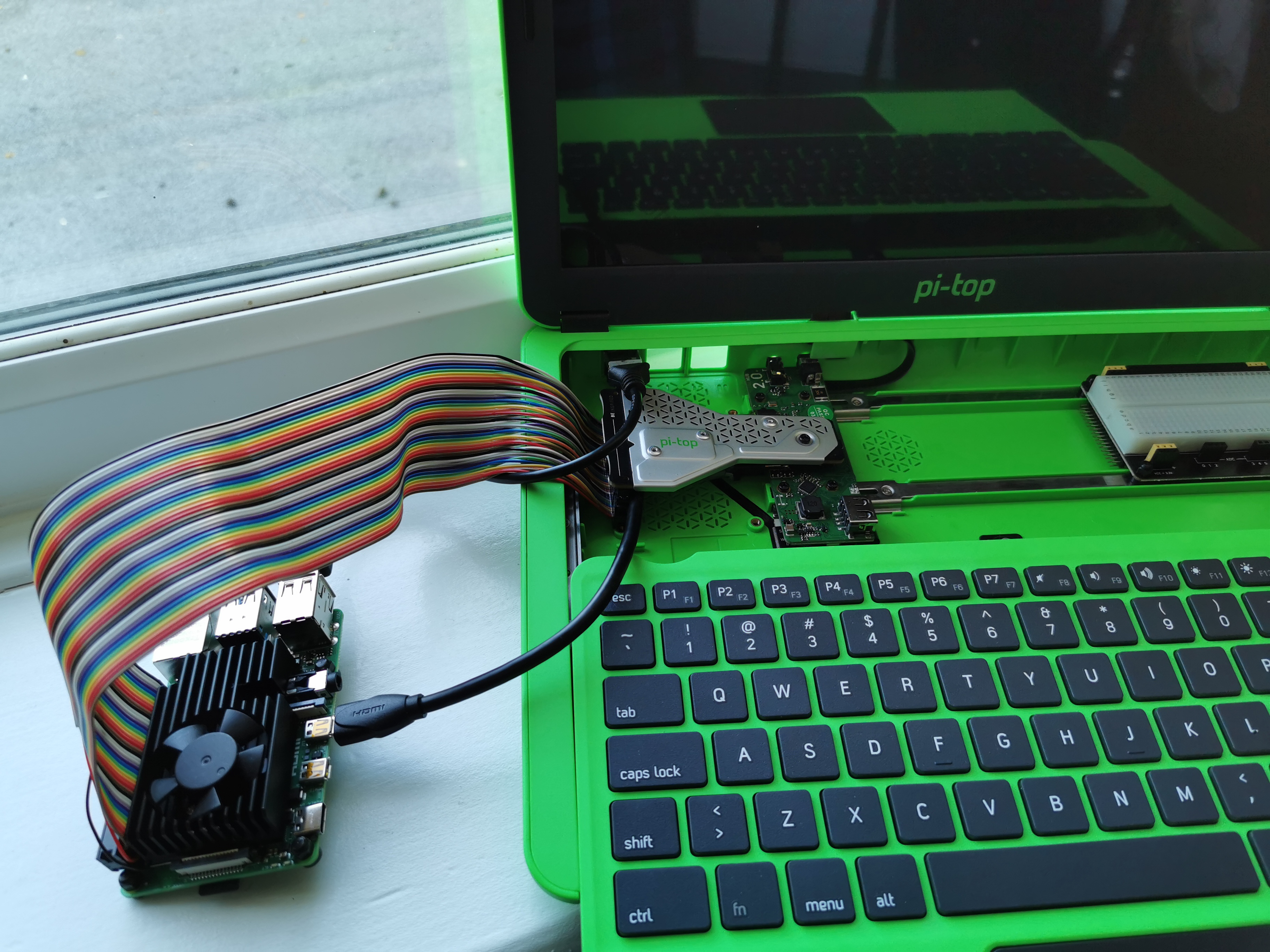
However, because of both of these mechanical issues, it means that the Raspberry Pi 4 can’t fit in the regular spot! The only other options are to fit it outside of the device completely or to mount it inside on the modular rail. Mounting it on the Modular Rail is another set of issues as I wouldn’t be able to use the pi-top Add-Ons, and the Ethernet connector would also interfere with the sliding keyboard. Although if I’m mounting the Raspberry Pi on the Modular Rail then I can’t use any of the add-ons anyway! For the purpose of this prototype the Pi will go outside so that I can use the Add-ons.
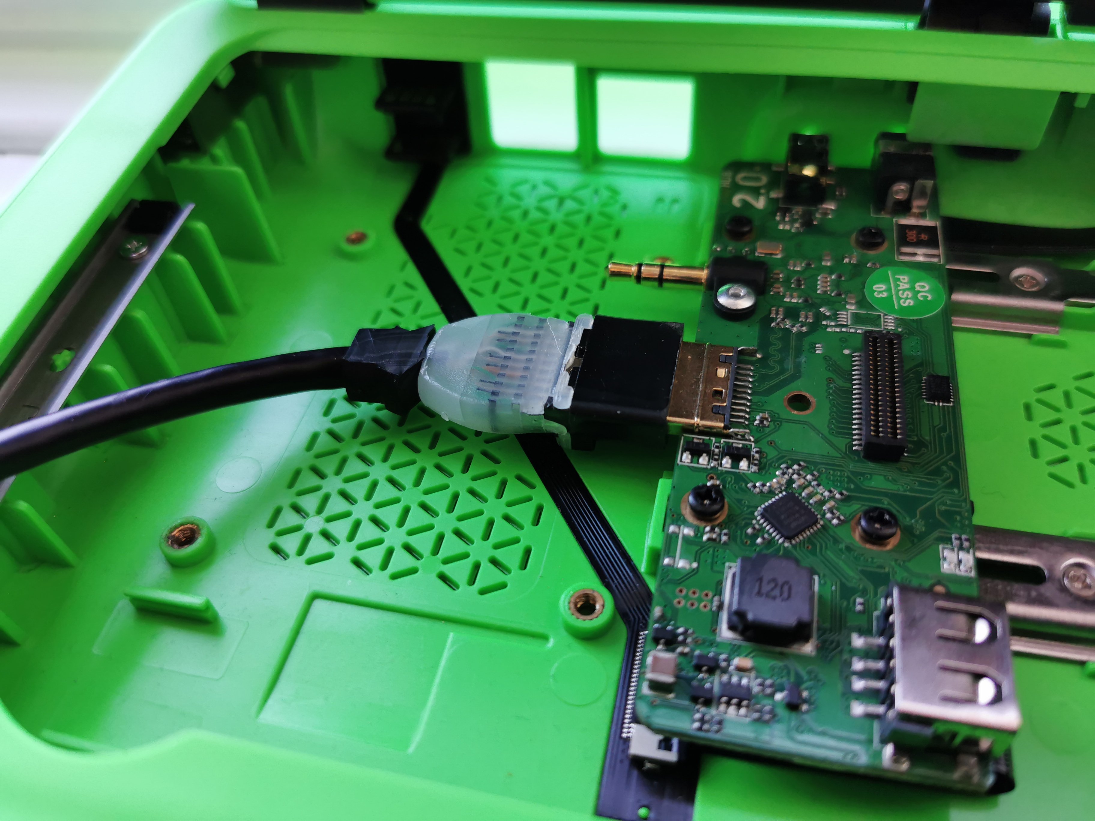
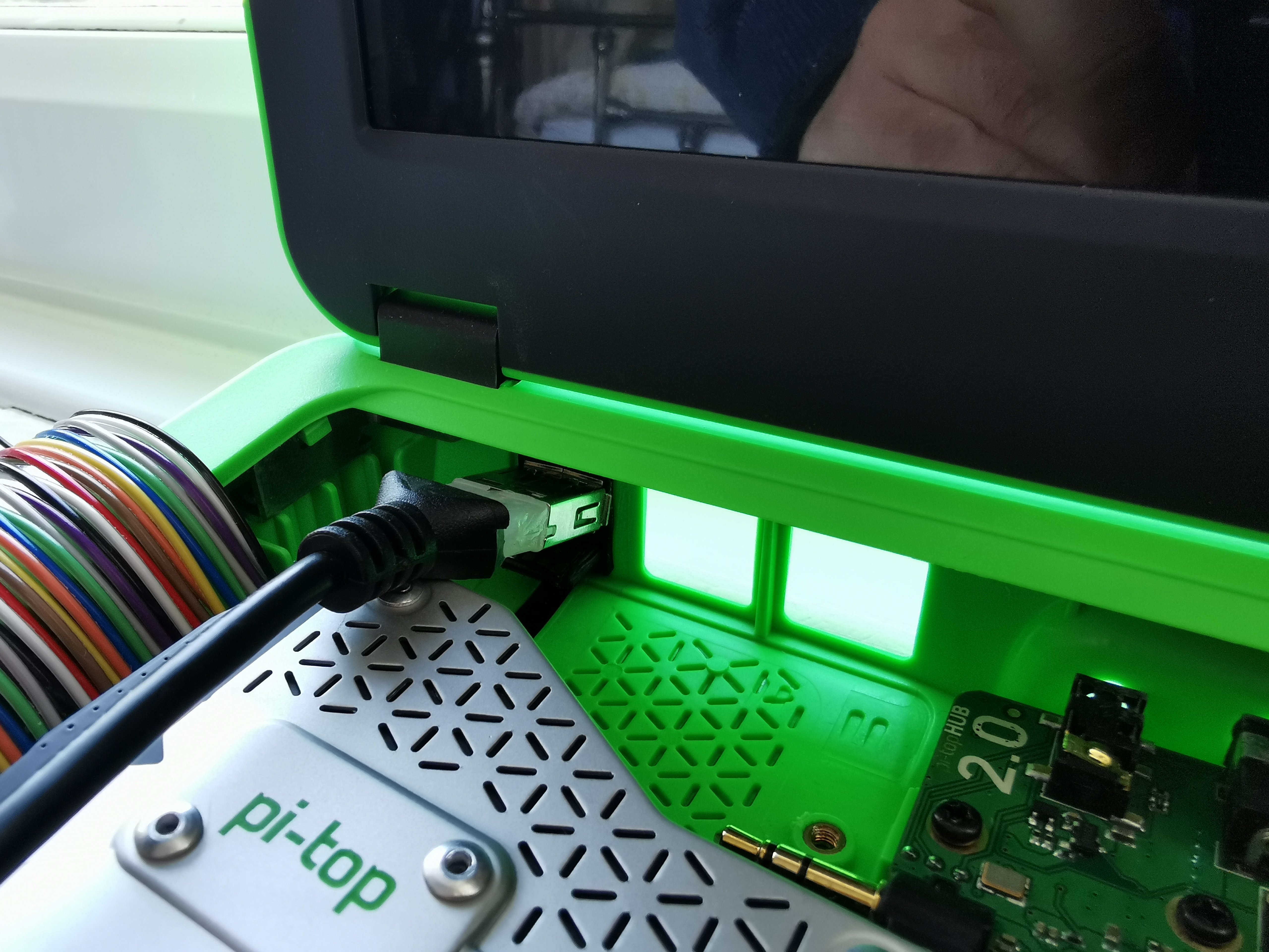
The first step is to connect up the HDMI cable into the HDMI Connector. The image shows that I’d stripped away the plastic over-moulding. That was because heatsink on the Cooling Bridge that conducts heat away from the Raspberry Pi interferes a little too much to connect the bridge to the Hub.
The cooling bridge needs to have the 40pin Ribbon Cable connected up. I had to sanity check which pin was connecting to which side a few times (Multimeter and continuity check). Best thing is to have pins with a max height of 3.51mm. Mainly so that the Cooling Bridge can mate to the Hub at the smallest angle possible. The one I had was from the pi-top [4] spare parts baggy so the pins stuck out a little more than intended.
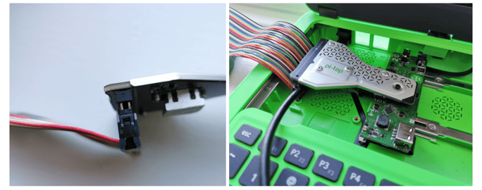
The third step is very similar to the first step: I would like to use the keyboard and trackpad so I’ll need to connect to the upper USB Plug. The rubber plugs can flex a fair amount, so there’s no need to worry about damaging them. Because of the length of over-moulding on the cable I’ve purchased, it interferes with the cooling bridge, so I’ve placed it in after the cooling bridge so that it may rest on that
Next thing is to connect all these cables up to the Raspberry Pi! I’ve tested the HDMI in both ports and it doesn’t seem to make a difference, so there is no preference there. Again, check the orientation of the 40p cable as it connects to the Raspberry Pi. Ribbon cables can come in multiple orientations, so measure twice and cut once. If you try to turn on the device and 5V goes down the wrong pin, it’s likely that pin won’t function as intended ever again.
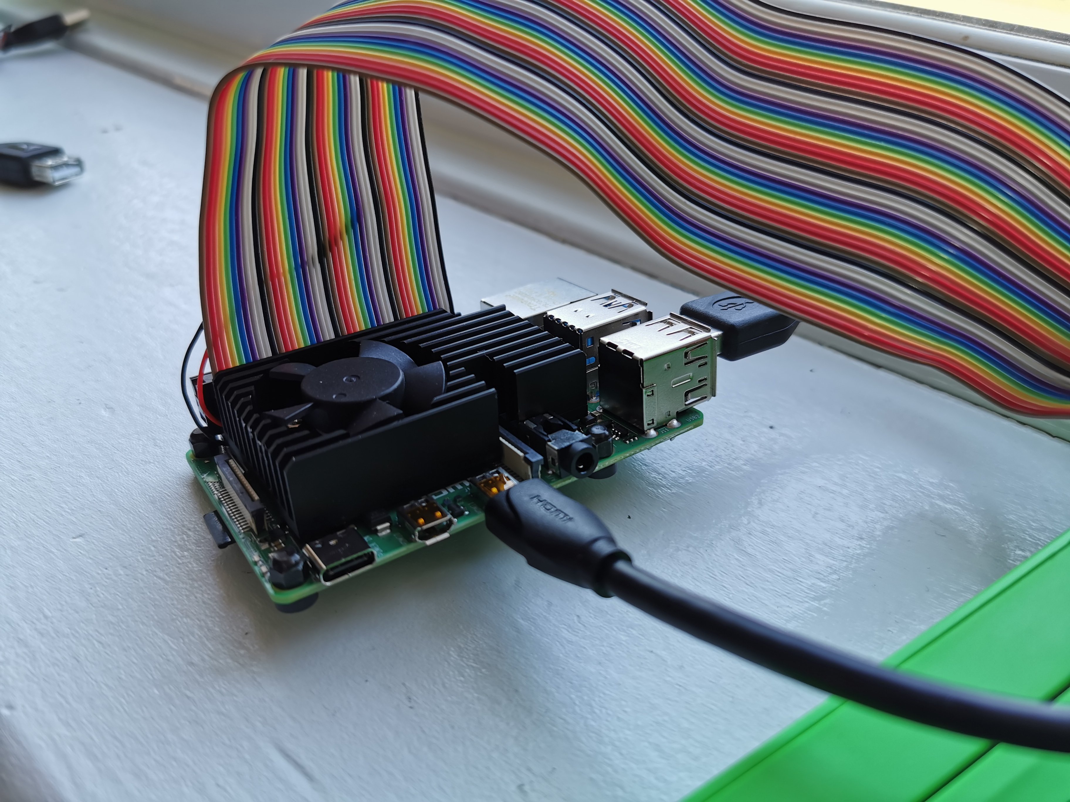
I’ve also added a large heatsink and fan, just so I can get the most performance from the Raspberry Pi (N.B. I’m aware the 5V and GND of the fan are not connected up as I’ve left my soldering iron in COVID-19 Territory).
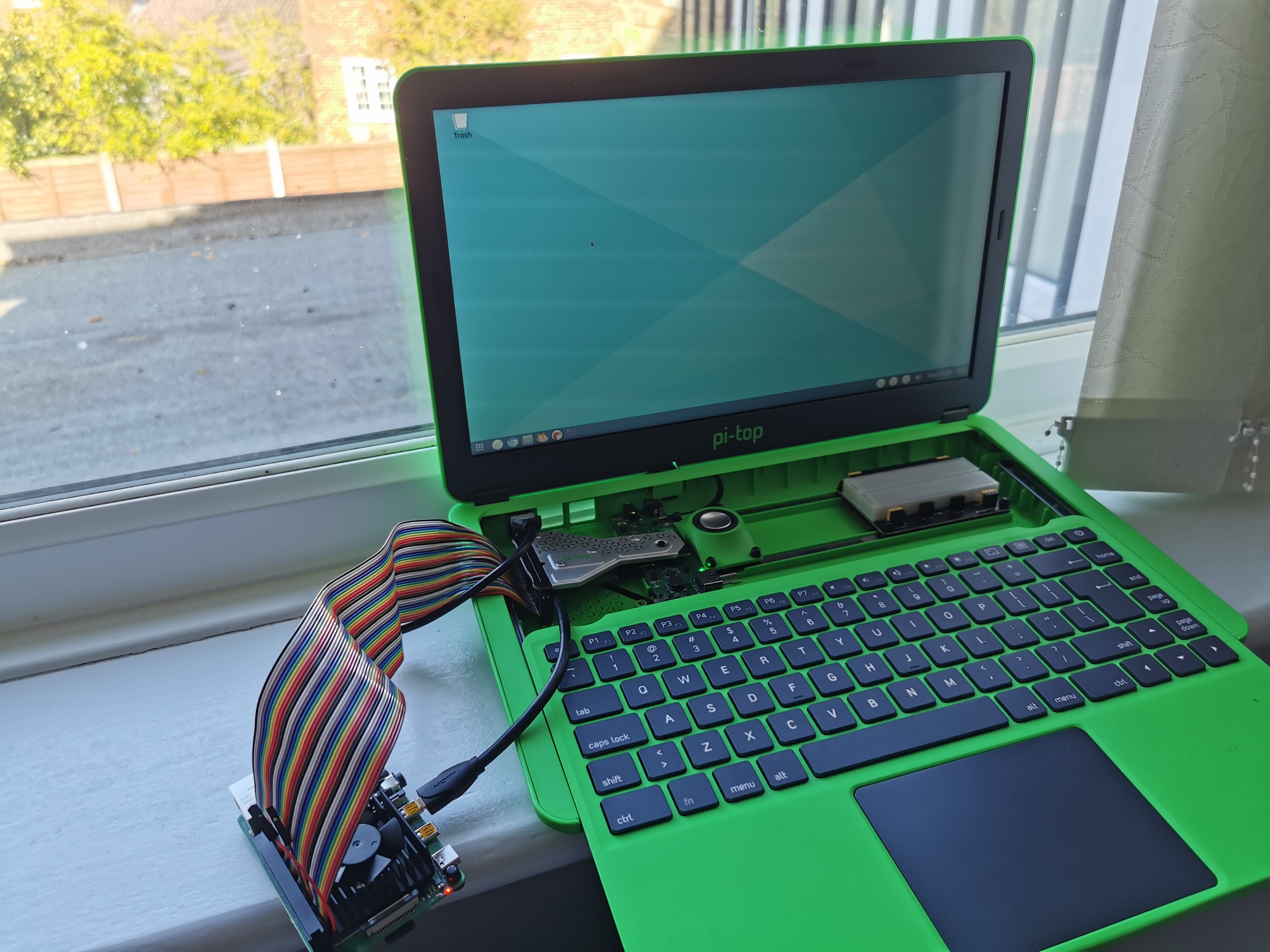
As with any new project, always good to check that the Power nets aren’t connected to the Ground nets with a multimeter (something that I’ve learnt the hard way). Once you’ve done that, press the power button and it’s up and running!
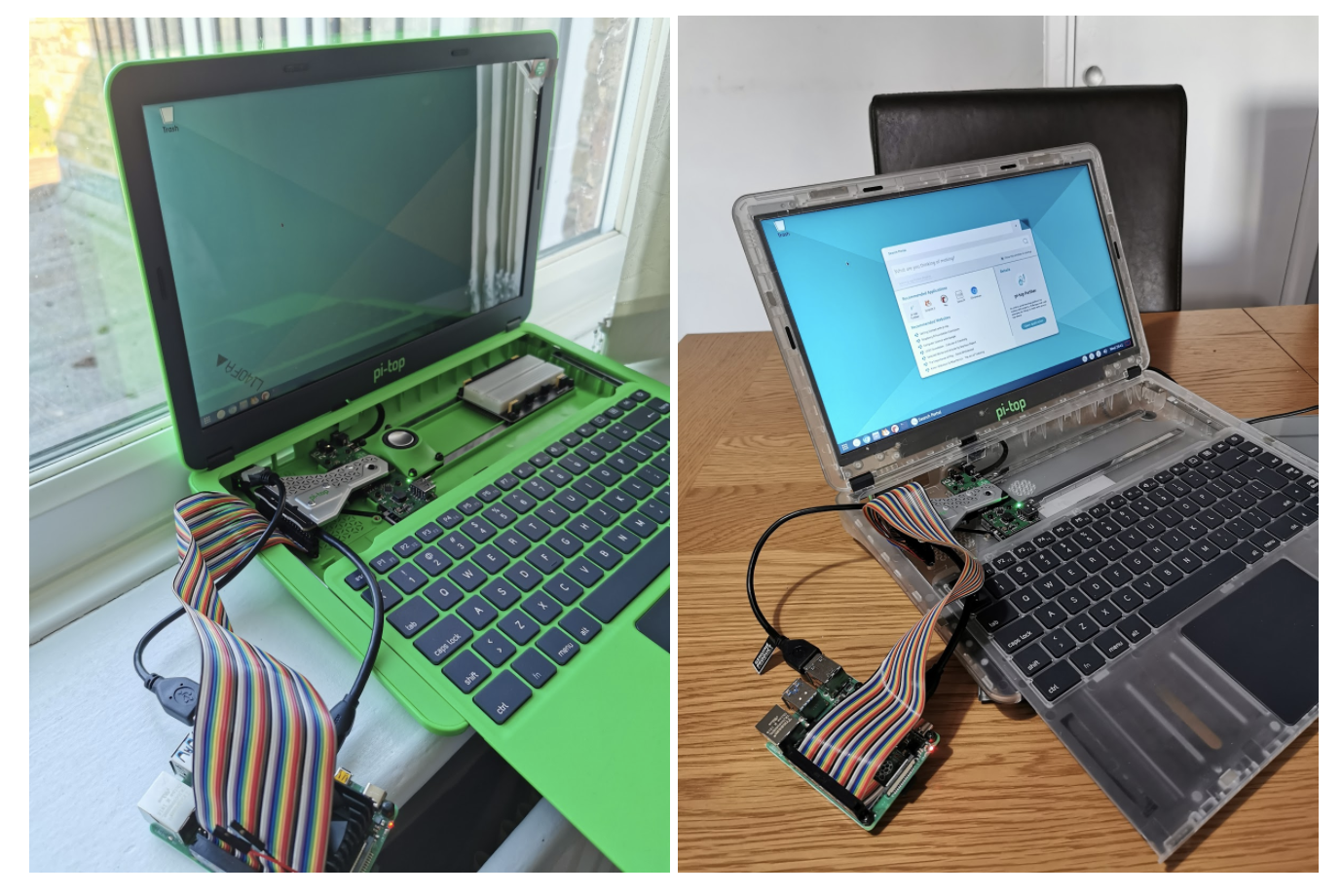
I built the first version in the transparent pi-top [3] all us pi-top employees get as gifts, and I built a second in the regular green pi-top [3]. It is all that simple!
I’m happy with the proof of concept, but there are major improvements to be made:
- Get the Raspberry Pi inside the device under the sliding keyboard
- Have 2 x pi-topSPEAKER_V2s in the rail
- Tuck the cables underneath the keyboard
- Breakout the 2nd micro-HDMI into the chassis (somehow)
- Connect the 3.5mm Audio Jack to the Raspberry Pi
I don’t get to do many side projects like this these days, but I’m very much looking forward to the next iteration. Let me know what you think of the build so far in the comment section or in the forum post and if you have any recommendations or thoughts on how it could be improved!